PLC (Lesson 2 -Basic Programming)


Allen Bradley PLC Programming With Studio 5000


This session fallowing task will be complete.

1.Create a new project
2. Write ladder logic
3. Use symbolic tag names
4. Use the tag monitor/editor

Creating New Project using Studio 5000


For details about softwear please visit rockwell automation official web site.

http://www.rockwellautomation.com/rockwellsoftware/products/studio-5000.page

* Go to start menu ->Rockwell Softwear -> Studio 5000
* Click & open


Creating a New Controller Project 


In this Secession, you will create an offline project using a CompactLogix 1769-L18ER controller.

1. From the Main window Select new project.Then next dialog box appear.


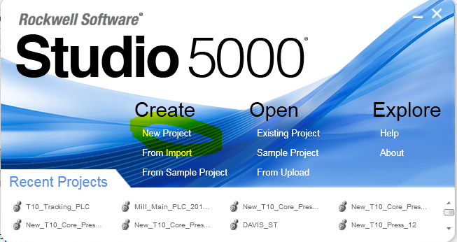
2. From next window please select controller Type.Type project name.Then click next.


3.Then new dialog box appear.Select revision & expansion module & click finish.


The Controller Organizer appears on the left side of the RSLogix5000 window, with a folder called
Controller Controller1.
At this time, there is no I/O, tag database, or logic associated with the controller

You have now created your first controller project!

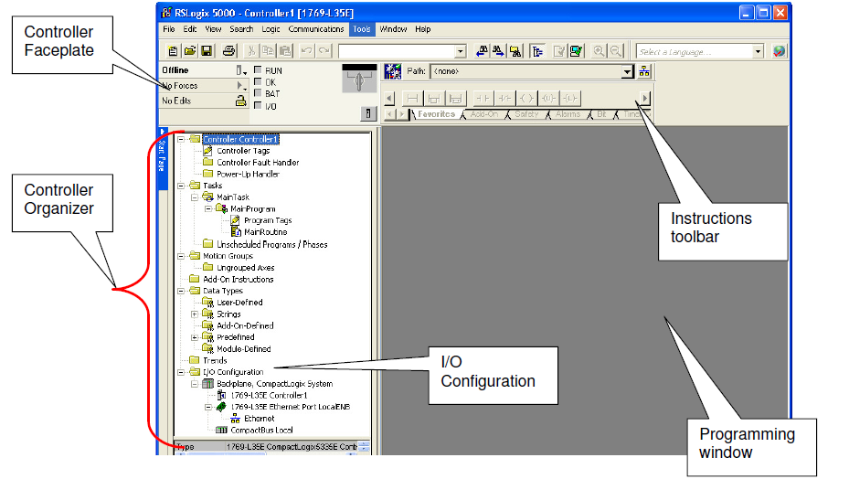
The Controller Organizer is a graphical representation of the contents of your controller
file. This display consists of a tree of folders and files that contain all of the information
about the programs and data in the current controller file. The default main folders in this
tree are:

Controller File Name
Tasks
Motion Groups
Add-On Instructions
Data Types
Trends
I/O Configuration

The square containing a ‘+’ or ‘-‘ indicates whether a folder is open or closed. Click
on it to expand the tree display and display the files in the folder. The - sign indicates
that the folder is already open and its contents are visible. By default the Add-On
instructions folder is empty as none are installed by default.


Adding Ladder Logic to the Main Routine

In this session  you will add code for a simple motor start/stop seal-in circuit. You will experience the ease of
programming with RSLogix 5000 software. During the session we will only utilize ladder logic programming,
but Logix controllers also can be programmed using Function Block, Sequential Function Charts, and
Structured Text. This allows you to select the program language that best fits an application.
You will continue to use the project already opened.

1. In the Controller Organizer expand the MainProgram folder by clicking on the +.

Once expanded, the MainProgram will appear as shown below:

2. Double-click the MainRoutine icon.then fallowing window appear.


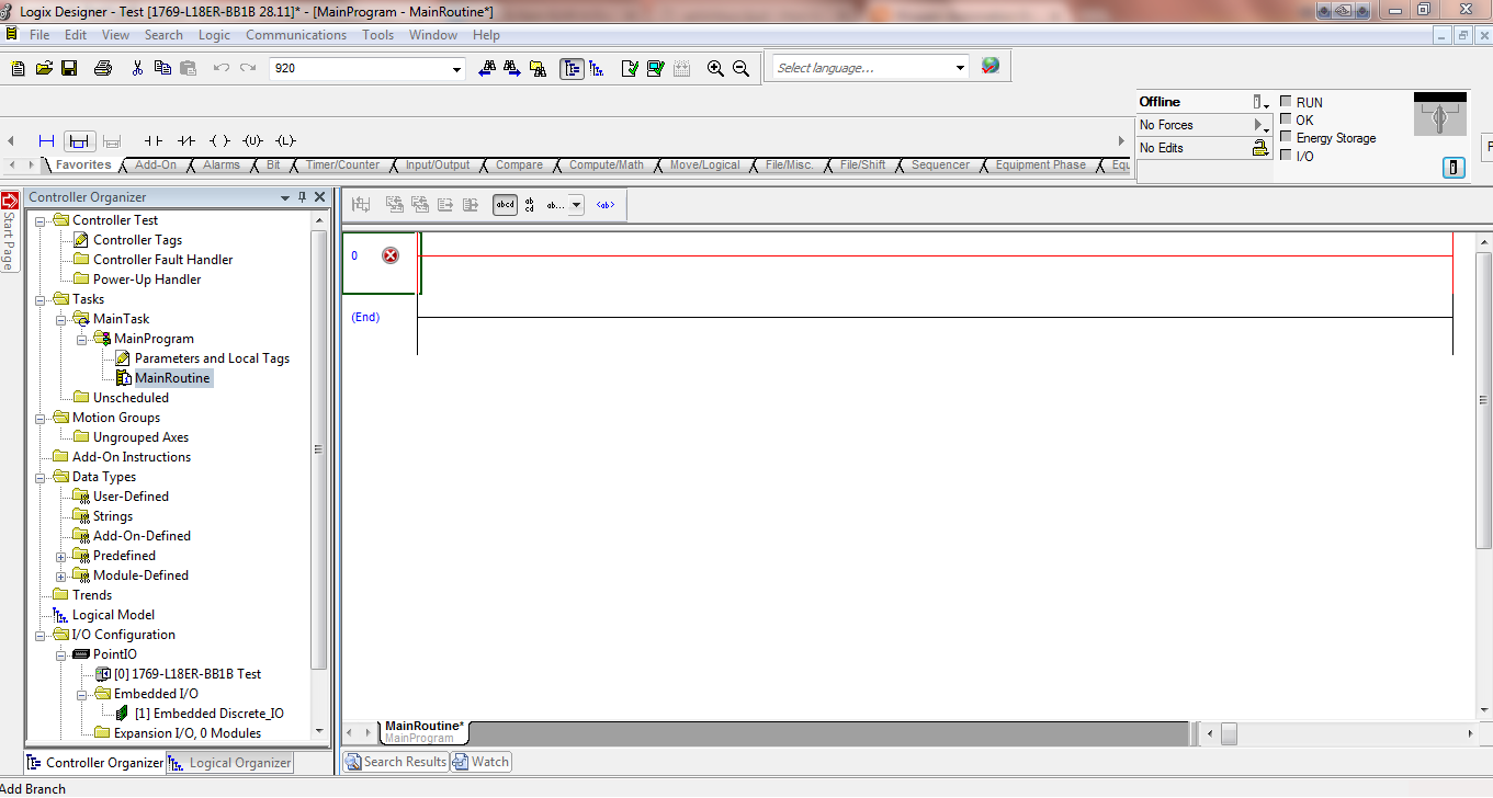
3. From the instruction toolbar, left click and hold on the Examine if Closed (XIC) instruction

4. Drag the XIC onto rung 0 until the green dot appears as shown above. Release the mouse button at the location you wish to place your instruction.

5. Verify your rung appears like the figure below

6. From the instruction toolbar left click and hold on the Examine if Open (XIO) instruction
7. Drag the XIO onto rung 0 to the right of the XIC instruction as shown above. Again a green dot will
appear to the right of the XIC instruction indicating where your new instruction will be inserted.
Release the mouse button at the location you wish to place your instruction.

8. Verify your rung appears like the figure below:

9. From the instruction toolbar, left click and hold on the Output Energize (OTE) instruction.


PLC (Lesson 1 -Introduction)


Introduction


              A programmable logic controllerPLC, or programmable controller is a industrial control system used for Automation of typically industrial processes, 
PLC has been applied in many sectors. Industrial Automation, Building automation, Office automation, Household automation, Transport automation, etc. 


The first Programmable Logic Controller (PLC) was developed by a group of engineers at General Motors in 1968, when the company was looking for an alternative to replace complex relay control systems.
The new control system had to meet the following requirements:
  •  Simple programming
  •  Program changes without system intervention (no internal rewiring)
  •  Smaller, cheaper and more reliable than corresponding relay control systems
  •  Simple, low cost maintenance.

Major PLC manufacturer

  • Allen Bradley


  •         Siemence
  •         Honeywell
  •         Modicon
  •        Omron
  •        General Electric
  •         Mitsubishi

Functions by a PLC

A programmable logic controller can be used to perform the following functions:

Control Type
Functions
1. Sequential Control
a)      Conventional Relay Logic Replacer
b)      Timers / counter
c)   Auto/ Semi-Auto/Manual control of machines/Processes
2. Sophisticated Control
a)      Arithmetic Operations (+ ,-, ´, ¸ )
b)     Information Handling
c)      Analogue Control (temperature., pressure)
d)     Stepper-motor Control
e)      Servo-motor Control
3. Supervisory Control
a)      Process Monitoring and Alarm
b)      Fault Diagnostics
c)      Interface with Computer (RS 232/ RS-422/Ethernet)
d)     Printer/ ASCII interfacing
e)      Local Area Network


 Hardware Configuration of a Programmable Logic Controller
A programmable logic controller system can be divided into the following blocks as shown below.


PLC Configuration

There are two PLC basic configurations that commercial manufacturers offer. that commercial manufacturers offer. 


  • „Fixed Configuration 


    • Modular Configuration


    Input/Output Modules


    PLC Operation

    The PLC operates internally in a way very similar to computers repetitively. 
    1. The states of the input devices are continuously monitored and copied from input module into input RAM memory area. 
    2. The CPU then executes the control program stored in the program memory area.
    3. Depending on the program and the states of inputs, the output states of the relevant output devices are then written into the output RAM memory area.
    4. At the end of each execution cycle, data in output RAM area are then copied to the output module.
    5. After each execution new cycle begins. (1)

    The time required by the PLC for a single execution of a program including the actualisation and output of the process image, is termed the cycle time. The longer the program is and the longer the respective PLC requires to process an individual program line, the longer the cycle. Realistic time periods for this are between approximately 1 and 100 milliseconds.


    Automation Element (Actuator-Pneumatic)

    Actuators

    1. Pneumatic Actuator

    Pneumatic
            using compressed air: operated by compressed air in a tool or machine
            physics involving compressed gases: relating to, operated by, or typical of the pressure of compressed gases, especially air pressure or compressed air

    Pneumatic is competing with two other working media
      • Electrics
      • Hydraulics

    Pneumatic components can perform the following types of motion:
      • Linear
      • Swivel
      • Rotary

    Some industrial applications employing pneumatic are:
    • General methods of material handling:
      • Clamping
      • Shifting
      • Positioning
      • Orienting
      • Branching of material flow
    • General applications:
      • Packing
      • Locking
      • Driving of axes door of chute control
      • Transfer of materials
      • Turning and inverting of parts
      • Sorting of parts
      • Stacking of components
      • Stamping and embossing of components.

    Energy Supply- Compressed air generation


    Compressed air is generated by compressors


    Compressor Types

    Description one by one about main compressor types.

    1. Diaphragm Compressor.

    technical definition simply means that a diaphragm compressor is an air compressor the uses the flexing of a rubber or silicone membrane to compress the air rather than a piston system. Conventional air compressors make use of a piston and crankshaft arrangement very similar to those found in a car engine to compress the air.


    Diaphragm Pump Animation


    Piston Compressor
    2. Screw Compressor.


    A positive displacement compressor consisting of one male and one female rotor which contain lobes that when meshed together reduce the amount of available space for the refrigerant gas to occupy, thus compressing it. The male rotor is usually the drive rotor.
                 
                          
                                 Screw Compressor working 3D animation       

    Air distribution

    In order to ensure reliable and trouble-free air distribution, a number of points must be observed. This includes primarily the correct sizing of the pipe system, but also the pipe material, flow resistance, pipe layout and maintenance.  
    For the production of compressed air, compressors are required to compress the air to the desired working pressure. Then, it supplied by a central line to various drives and components. The compressor and the distributing system can be arranged as follows to achieve a proper air supply.  


    Pipe types
    ·         Steel
    ·         Glued Plastic
    ·         Stainless Steel
    ·         Aluminum


    Tube Types

             Polyurethane tubing
             Nylon tubing
             Polyethylene tubing
             Braided PVC hose
             Self-fastening hose
             Recoil tubing
             Anti-spark tubing


    Why compressed air preparation? 
    • The maximum water content of air (100% relative humidity) is highly dependent on temperature. Air can only absorb a certain quantity of water per volumetric unit (in m3), irrespective of pressure. The warmer the air, the more water it can absorb. Excessive humidity manifests itself as condensation. If the air temperature drops from 20 0C to 3 0C, the maximum water content of compressed air is reduced from 18 g/ m3 to 6 g/m3. The compressed air can now no longer absorb more than aprox. 1/3 of water, i.e. the relative air humidity is tripled. If the level of air humidity is to remain the same, the excess 12 g/ m3 must be removed from the air. 


      Class
      Solids
      Water Content
      Oil content
      Max. Particle size(mm)
      Max.Particle Density(mg/m3)
      density
      (mg/ m3)
      Max. dew point (0C)
      Max. oil density
      (mg/m3)
      1
      0.1
      0.1
      0.003
      -70
      0.01
      2
      1
      1
      0.12
      -40
      0.1
      3
      5
      5
      0.88
      -20
      1
      4
      15
      8
      6
      +3
      5
      5
      40
      10
      7.8
      +7
      25
      6
      -
      -
      9.4
      +10
      -
      7
      -
      -
      -
      -
      -


      Water condensation


      Water is always preventing in air in the form of natural air humidity. During the cooling of compressed air, water is released in large quantities. Drying helps to prevent corrosion damage in compressed air system and in the connected consuming devices.

      Oil contamination
      Similarly. In the case of oil-free operating compressors, oil aerosols present in the drawn-in air also lead to a corresponding residue of oil pollutants. However, this oil is not suitable for the lubrication of drives and can even lead to the clogging of sensitive parts.

      Dirt and rust particles
      Solid particles occur in the form of dust (carbon black, corrosion particles) primarily in agglomeration points.
      Coastal regions, in general, have lower level of dust, but instead contain additional salt particles resulting from evaporated seawater droplets. Dust is classified into categories of particle size, i.e. coarse dust (>10 micron), fine dust (1 to 10 micron) and atomised dust (< 1 micron).

      How clean compressed air should be?
      The answer is quite simple: compressed air must be so clean that it cannot cause any malfunctions or damage. Contamination accelerates wear on sliding surfaces and seal elements. This can affect the function and service life of pneumatic components. As each filter also creates a flow resistance, compressed air should be as clean as possible for economic reasons.

      Function of service unit
      The individual functions of compressed air preparation, i.e. filtering, regulating and lubricating, can be fulfilled by individual components. These functions have often been combined into one unit, i.e. the service unit. Service unit are connected upstream of all pneumatic systems.
      Generally, the use of a lubricator is not necessary in advanced systems. This is to be used for specific requirements only, primarily in the power section of a system. Compressed air in a control section should not be lubricated.

    What is Automation


    Objective Of the Automation 

    Automation is aimed at reducing human effort in performing a task.   


    What is automation?


             •Automation is the use of control systems such as computers to control machinery and processes, replacing human operators.
          •It is a step beyond mechanization, where human operators are provided with machinery to reduce the physical requirements of work and  the need for human sensory and mental requirements.

    Refer Video for get an idea


    Where used?

    •Production Industry
    •Offices
    •Buildings
    •Construction Industry
    •Medical field
    •Household equipment
    •Aerospace Industry
    •etc..


    Industrial Automation Element


    i. Actuators  (Pneumatic, Hydraulic, Electrical)
    ii. Sensors  (Binary, Analog, …)
    iii. Processors  (PLC, IPC, Microcontrollers, relays, pneumatic-hydraulic controllers)
    iv. Network  (Machine-Machine communication, digital Cables, Ethernet, ProfiBUS-DP ..)
    v. Software  (Human-Machine-Interface, Controller programming, visualization)

    Next Blog Description About Automation Element